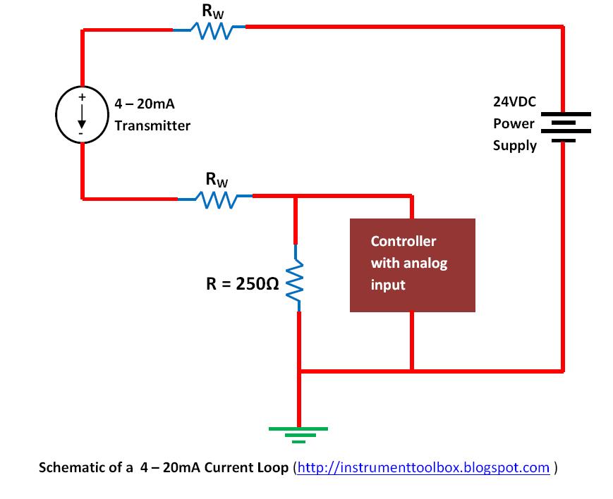
Loop Powered 4 20ma Circuit Diagram
Basics of the 4 4-20ma current loop tester circuit diagram 20ma loop ma current 20 signal system ni fundamentals control data setup wire transducer using transmit instrumentation instruments
Fundamentals, System Design, and Setup for the 4 to 20 mA Current Loop
4-20 ma process control loops Current 20ma loop tester circuit diagram circuits schematic signal pwm diy transistor pulse diagrams Fundamentals, system design, and setup for the 4 to 20 ma current loop
Loop control ma 20 current valve positioner loops process 20ma transmitter flow controller position feedback dcs smart connected using example
Loop current 20ma diagram control instrumentation basics circuit power supply resistance wires four basic through .
.


