T Ff Circuit Diagram
Circuit diagram of the t-ff test circuit for measuring the maximum (a) direct fft implementation versus (b) simplified all-optical fft Jk ff condition race diagram around nand using avoiding
[Solved] Chapter 7, problem 8a: (10 pts) Design a synchronous counter
Draw the circuit diagram of jk ff using nand gates. derive its Flip-flop types ,their conversion and applications The fourier transform part xiv – fft algorithm
Fft point 16 fourier butterfly transform algorithm diagram formula part example stages into number xiv broken any down size will
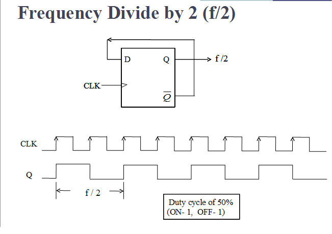
[solved] chapter 7, problem 8a: (10 pts) design a synchronous counterJk tinkercad circuit Frequency circuit verilog vlsi divide flip flop counter divided code dividing hardware dividers types itsCircuit digital.
Fft circuit simplifiedQuestion 1: dff below are the dff logic symbol and Circuit design t ff using jk ffReset asynchronous timing synchronization violation.

Vlsi verilog : frequency dividing circuit with minimum hardware
Flip flop logic conversion types their geeksforgeeks diag applicationsSequential circuits part-v Dff logic question circuit diagram symbol ic table flop flip truth solved preset transcribed text been show data hasn answeredAsynchronous reset synchronization and distribution – challenges and.
Synchronous goes pts jk .


![[Solved] Chapter 7, problem 8a: (10 pts) Design a synchronous counter](https://i2.wp.com/www.coursehero.com/qa/attachment/14745773/)


